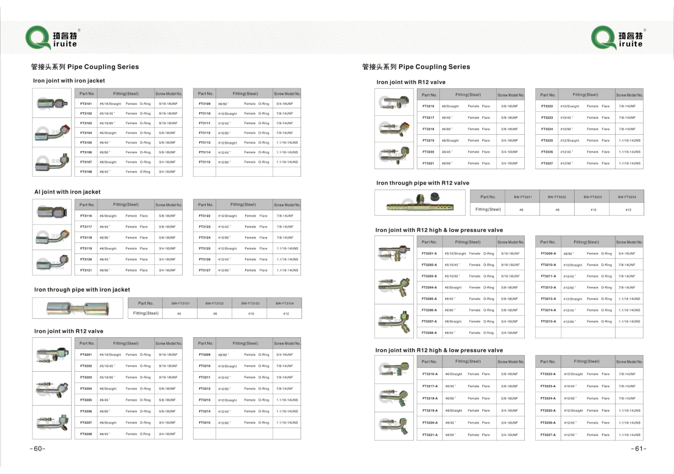
ford 555 backhoe power steering hose diagram
Understanding the Ford 555 Backhoe Power Steering Hose Diagram
The Ford 555 Backhoe is a versatile piece of machinery often used in construction and landscaping. One crucial system within this machine is its power steering system, which allows operators to maneuver the backhoe with minimal effort. A vital component of this system is the power steering hose, which plays a significant role in directing hydraulic fluid from the power steering pump to the steering mechanism. Understanding the layout and function of this hose can be beneficial for mechanics and equipment operators alike.
Overview of the Power Steering System
In the Ford 555 Backhoe, the power steering system is designed to enhance the ease of handling the machine. It accomplishes this by using hydraulic fluid to amplify the force exerted by the operator on the steering wheel. When the operator turns the steering wheel, the power steering pump generates hydraulic pressure, and this pressure travels through hoses, including the power steering hose, to move the steering cylinder.
Importance of the Power Steering Hose
The power steering hose is integral to the system's functionality. It must withstand high pressure and maintain an uninterrupted flow of hydraulic fluid. If the hose becomes damaged or develops leaks, it can lead to reduced steering performance, increased wear on other components, or even complete failure of the steering system. Regular inspection and maintenance of the steering hoses are crucial to ensure the longevity and reliability of the power steering system.
Analyzing the Power Steering Hose Diagram
ford 555 backhoe power steering hose diagram

The power steering hose diagram for the Ford 555 Backhoe offers a visual representation of the entire hydraulic steering system. Typically, the diagram illustrates important components such as the power steering pump, steering gear, hydraulic reservoir, and the hoses connecting these elements.
1. Components Identification The diagram labels each part of the system, helping technicians locate components quickly during inspection or repairs. Commonly identified parts include the high-pressure hose, return hose, and any associated fittings.
2. Flow Direction An essential part of the diagram is the depiction of fluid flow direction. Understanding the path that hydraulic fluid takes—from the pump through the steering mechanism and back to the reservoir—is vital for diagnosing issues within the system.
3. Schematic Representation The diagram usually presents a simplified version of the system, making it easier to understand complex interactions. Each line represents a hose, with arrows denoting flow direction, while circles may indicate connection points or components.
4. Maintenance Indicators Some diagrams will also include notes or symbols indicating recommended servicing points or potential areas prone to wear, helping operators identify where to focus their maintenance efforts.
Conclusion
In summary, the Ford 555 Backhoe power steering hose diagram is an essential tool for anyone involved in the maintenance or operation of this machinery. By understanding the components and flow of the hydraulic steering system, operators can ensure smooth and efficient operation. Regular inspection and timely replacement of the power steering hose and related components can prevent costly repairs and downtime, ultimately leading to a more productive and reliable machine. Whether you are a seasoned mechanic or a new operator, familiarizing yourself with the power steering hose diagram will enhance your technical knowledge and improve your ability to maintain and operate the Ford 555 Backhoe effectively.
-
Ultimate Spiral Protection for Hoses & CablesNewsJun.26,2025
-
The Ultimate Quick-Connect Solutions for Every NeedNewsJun.26,2025
-
SAE J1401 Brake Hose: Reliable Choice for Safe BrakingNewsJun.26,2025
-
Reliable J2064 A/C Hoses for Real-World Cooling NeedsNewsJun.26,2025
-
Heavy-Duty Sewer Jetting Hoses Built to LastNewsJun.26,2025
-
Fix Power Steering Tube Leaks Fast – Durable & Affordable SolutionNewsJun.26,2025

